Valve Electric Diagram
Plc valve control ladder logic Valve hydraulic control symbols directional symbol valves center position closed spring four blocked circuit ports flow which pressure between pdf Wiring gas diagram fan limit valve switch honeywell control voltage low wire motor furnace white rodgers installation thermostat heater furnaces
From Signal to Movement: Electro-Pneumatic Process
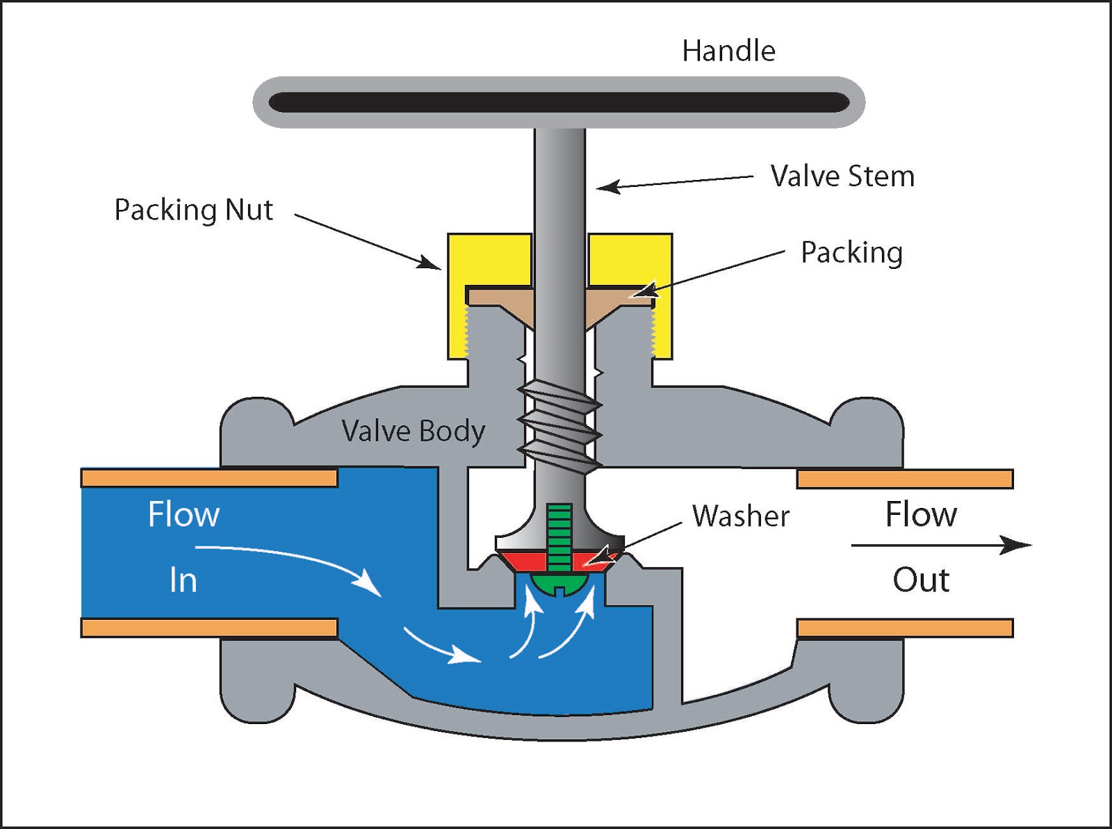
Low voltage motor wiring Solenoid hc valve controller hydrawise Valve working principle globe plug labels basic
Directional control valves symbols
Heating plan wiring system central landis gyr diagram hive gif instructions controls boiler only diagrams controller programmer manual flameport waterRobertshaw millivolt maxon Control valve positioner circuit diagramWiring honeywell wire thermostat underfloor boiler combi motorised danfoss actuator ambrasta sponsored links.
Valve wiring position mid diagram sponsored linksValve plc off control logic ladder controls relay barrier concept instrumentation tools programming instrumentationtools Robertshaw millivolt gas valve wiring diagramHoneywell 6 wire thermostat wiring diagram.

Y plan central heating system
Positioner valve principle electropneumatic schematic pneumatic converter working vrc coupled manifoldValves actuator positioner instrumentation functions instrumentationtools principle process breather From signal to movement: electro-pneumatic processMid position valve wiring.
.


